
Unlock the Secrets of the TIP120: Your Gateway to Mastering Circuit Design!
The TIP120 Darlington pair transistor is a remarkable component that has captured the attention of both novice and experienced electronics enthusiasts. Its unique design and functionality make it an essential tool in the world of circuit design. Whether you are building a simple project or diving into more complex designs, understanding the TIP120 can be your gateway to mastering a variety of applications. Its popularity stems from its ability to amplify current and provide high switching capabilities, which makes it a go-to choice for many. In this article, we will explore the TIP120's specifications, applications, and how to effectively use it in your own circuit designs.
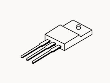
Understanding the TIP120 Darlington Pair Transistor
The TIP120 belongs to a category known as Darlington pair transistors, which are designed to provide high current gain. Essentially, a Darlington pair consists of two bipolar junction transistors (BJTs) connected together in a manner that amplifies the current from the first transistor through the second one. This configuration allows the TIP120 to achieve a current gain that is significantly higher than that of a single transistor. A personal experience I had with the TIP120 was during a project where I needed to control a motor. The high gain of the TIP120 made it possible to switch the motor on and off with just a small control signal, showcasing its effectiveness in real-world applications. The TIP120 is designed to handle higher currents and voltages, making it versatile for various uses.
Specifications of the TIP120
The electrical specifications of the TIP120 are impressive and contribute to its popularity. It has a maximum collector current rating of 5 A and can withstand a collector-emitter voltage of up to 60 V. One of the standout features is its current gain (hFE), which can reach values as high as 1000, depending on the operating conditions. This means that even a small input current can control a larger output current effectively. Additionally, the TIP120 has thermal characteristics that allow it to operate safely within a range of temperatures, typically from -55°C to +150°C. Understanding these specifications is crucial when designing circuits that require reliable performance under different load conditions. Friends of mine who have used the TIP120 in their projects often remark on how its robust specifications allow for a wide range of applications without the need for constant recalibration.
Applications of the TIP120
The TIP120 is utilized in various applications, primarily due to its ability to switch and amplify signals effectively. It is frequently employed in switching applications, such as controlling motors, lamps, and other high-power devices. For instance, in hobbyist robotics, it can drive motors based on low-power signals from microcontrollers. Additionally, the TIP120 is used in amplification applications, where it can strengthen weak signals, making it suitable for audio applications and sensor interfacing. From my own perspective, I have seen the TIP120 used in LED dimming circuits, where it helps control the brightness of lights through pulse width modulation (PWM). Its integration into different circuit types showcases its versatility and the breadth of its applications, making it a staple component for electronics enthusiasts.
Using the TIP120 in Circuit Design
Incorporating the TIP120 into your circuit designs is relatively straightforward, but there are best practices to follow to ensure optimal performance. One common application is using the TIP120 as a switch for controlling motors. To do this, connect the emitter to the ground, the collector to the motor, and the base through a resistor to your control signal. It is important to note that the resistor value should be chosen to limit the base current, typically in the range of 1kΩ to 4.7kΩ, depending on your input signal voltage. Additionally, using a flyback diode across the motor terminals can protect the TIP120 from voltage spikes generated when the motor is turned off. Friends of mine who have built projects around this transistor often share how following these best practices has led to reliable and efficient circuit designs. Experimenting with different configurations and loads can yield interesting results and deepen your understanding of how the TIP120 can be utilized in various scenarios.
Recap: The Versatility of the TIP120
In conclusion, the TIP120 Darlington pair transistor is a powerful tool in the realm of circuit design, offering high current gain and versatility for a wide array of applications. From switching and amplification to integration in complex circuits, the TIP120 proves to be a valuable component for both beginners and seasoned electronics enthusiasts. Understanding its specifications and best practices for usage will not only enhance your circuit design skills but also empower you to undertake more ambitious projects with confidence. As you delve deeper into the world of electronics, the TIP120 can be your trusted ally, helping you unlock new possibilities and master the art of circuit design.